INTRODUCTION
A Surveillance Camera is widely used to monitor a particular location or a part of a building, a camera will grasp the happenings that happens within the range of its focus and sends them in the form of video to a server or a display. A Camera must need a light source to clearly picture and send the data to the monitor or server, for normal purpose inside a building the camera will use normal light sources such as tube lights and other bulbs fixed for general lightening in nights and normal visible light from sun in day time .
A camera will use the visible light from sun in day time as light source in out door surveillance purpose and in night time we have to fix artificial light sources such as focus lights. for surveillance purpose we can use normal focus lights but if a focus light is fixed near camera the intruder may find the presence of a camera and he may use some techniques to avoid him from getting picturised in the camera. So we can use an invisible light ( For normal human eyes ) such as Infra Red rays as light source for the camera, so that the camera will be hidden and the light emitted by the light source also invisible and so the intruder will not be aware of the presence of a surveillance system inside the campus. Whereas the camera can view the IR rays and use it as light source to picturise the happenings within its focus.
THE CONCEPT OF NIGHT VISION
The concept of night vision is on demand on the present world military and surveillance scenario; because all countries and organizations are aware of the proxy methods of intrusion and are in need of avoid those intrusions to reduce losses.
The night vision is a concept in which the light source of the camera that we are using should not be visible to the normal human eyes and must be visible to the camera.
There are many invisible electromagnetic rays as already described and they are given below for reference.
1. Radio Waves
2. Micro Waves
3. Ultra Violet rays
4. Visible light spectrum ( bundle and not falls under invisible light source )
5. Infra red rays
6. X rays
7. Gamma Rays
In the above mentioned rays we should have to neglect the visible light spectrum as our basic concept is the light source should not be visible to the intruders who pass through the focus of the camera.
Radio waves and microwaves are merely waves and they follow the principles as visible light follows, but they can not reproduce images directly to a camera and so they can not be used as their energy level is very low to generate voltage in the camera image sensor
The Ultra violet rays are also falls under the same category as the micro waves and radio waves does. So we cannot use UV too.
X rays and Gamma rays are highly hazardous to human and living beings and so we cannot use that rays too and more over the artificial production of X rays and Gamma rays are very costly and hence forth the cheap and best method is using IR rays as they are cheap to generate artificially and will not create any hazardous to the living beings health.
HOW A DIGITAL CAMERA ACTUALLY WORKS
A Digital camera has a Sensor called imaging sensor, that can be made of two types one is CCD and other is CMOS, the Light source falls on an object will be always reflected or refracted or observed, a camera pointed towards an object will be hit by the reflected light from the object.The light hit the camera will fall on the camera lense and the camera lense will converge the image and make the refracted converged image on the image sensor and the image sensor will produce analog signals based on the reflected light falls on it.
Each and every object has its own reflection property, if a material looks like blue color the original thing is the material will observe all colors from the white light and reflects only blue colour, each and every colour has its own wavelength, the variation in colour is nothing but the variotion in wavelength, the wavelength is related to frequency of the light wave and this frequency is related to voltage and current and so the image sensor can produce a voltage based on the color of the light.
The produced voltage by the image sensor will be converted in to digital signals by using a analog to digital convertor and given as input for digital signal processor, the digital signal processor will convert the digital signals in to Display and or Storage output and sent to the display and or storage systems correspondingly. The display system or the storage system will receive the signals provided by DSP and display or store it correspondingly.
THEORY OF IR AIDED NIGHT VISION CAMERA
A camera will record an abject as image only if a light from light source falls on an object and reflected to the camera lens, in Day Time as there is enormus sun light available indoor and outdoor, the objects will reflect the sun light fall on it and so the reflected light if falls on the camera lens the camera will record the object that reflects the light, but in Night time there will not be sunlight and so there is a need for an artificial light source, if we want the camera to be hidden and then we cannot able to use visible light to avoid the intruder to know about the presence of camera.
Infra red rays are invisible to human eyes due to the lack of sensitivity to human eye against IR but visible to a camera as the image sensor can sense IR, In our project we are about to use an IR light source as artificial light source when there is no sun light available , so that the IR light will be made to spread through the focus area of the camera and the object which reflects the IR rays will get recorded on camera, the main fact is without a light source a camera cannot record, also human eyes cannot view an object.
PROPERTIES OF INFRA RED RAYS
The Infrared region of the spectrum lies beyond the red end of the visible range, wavelength of the IR rays will be above 750 nm Infrared rays will produce heat on the object on which it falls, Infrared rays follows the same principle in reflection, refraction and obserbtion, Infra red rays are invisible to human eyes as the human eye can sense the rays with wavelength ranging from 380nm to 750 nm. A camera can sense Infra red rays as the imaging sensor can detect the wavelenths above 750 nm up to an extent. Instead of using UV rays which is also an invisible light ray we are using IR for night vision as the wavelenth of the IR rays are very much higher than UV rays and so it can travel long distance when compared to UV rays.
IR SOURCE USED FOR OUR GADGET – ARRAY OF IR LEDs
As we are about to artificially generate IR radiations we have to assemble a IR source we are using an array of IR 10 mm IR LEDs which emmits IR radiations with wavelength of 950 nm, the IR LEDs are 3v and so we are connecting 4 LEDs in series with a 1 K resistor in series to avoid LED failure due to high current.
Totally 20 LEDs will be used arround the camera in 4 X 5 dimension which will emit IR radiations on the objects present right opposite to the camera, If the object present opposite to the camera on which the iR radiation felt may or may not reflect the radiation, if an object reflects the radiation, it will come back to the camera lens again, as the direction of the camera and dirction of the IR LEDs are same. The camera lens will converge the radiations and make It to fall on image sensor, the image sensor in turn produces analog waves that will be in turn converted as digitalsignals by the Anolog to digital coverter. The digital signals will be sent to DSP, which processes the signals and send signals to display and or storage system where it will be shown / stored as video
POWER SAVING MEASURES BY USING A LDR BASED CONTROLLER
By default if a night vision camera is fixed on outoors to monitor intrusion, the camera will use the sun light as light source and there is no need for IR radiations. If the IR source ( LED array ) is on it will consume considerable amount of power which will reduce the battery backup. To avoid this we are using a LDR based controller which will sense the lack of visible light source in the environment and switch on the IR LED array, the IR LED array will emmit IR radiations which is invisible to human eyes but visible to camera.
When the visible light ( sun light ) is available in the environment the LDR will sense the same and switch off the LED array.
LDR is a Light Dependant Resistor whose resistance will get reduced when the visible light falls on it and allows current to pass through it. The 555 IC is the main controller which will switch the relay on, the relay passes the 12 v current to the LED array. The IR LED array in turn emmits IR rays.
MAKING OF THE IR SOURCE :
IR SOURCE
IR radiations are by default emitted by hot bodies such as Sun which is the major IR source for earth. To generate IR radiations artificially we have to depend on normal filament lamps with specialized visible light filters. But it will not be a correct solution for what we are looking. The visible light filters can not able to filter all visible lights and a small trace of visible light can be seen from the artificial light source which is not preferred for the purpose of Night vision surveillance.
To overcome this we have selected a pure IR source for the purpose of zero visible light traces form the light source. The solution is the IR LEDs which are used for IR based remote controllers. But a single IR LED can not produce much enough intensity of light
So we have to build an array of IR LEDs which are all joined together to produce sufficient intensity of IR light and the produced IR light is completely pure and there will be zero visible light traces from the source provided the LED array is build with proper voltage calculation by connecting a fixed number of LEDs in series with a calculated value of resistor.
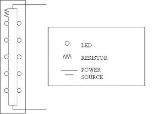
A general purpose dotted PCB is cut with 1 CM width and 10.5 CM height, an array of 2 columns and 5 rows of LEDs are fixed with the board. The LEDs are connected in series column vice and the two columns are connected in parallel with each other as shown in the below block diagram.
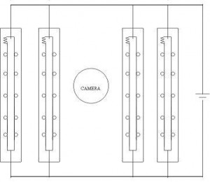
The above mentioned diagram shows how an array of LEDs is connected with resistor and a power source with 2 columns and 5 rows. 4 such array comprised of 40 LEDs totally are used to form this artificial, pure and controlled IR source.
The normal power supply we are applying to the 5 boards and each board contains two columns with each columns contains 5 LEDs connected in series and all columns are connected in series totally 40 LEDs is 12 V and 1 A . Each IR LED will consume 2 V as the LEDs in the same column are connected in series with each other the effective voltage consumption will be 10 V and the remaining 2 voltage will be shared among all the 5 LEDs of the same column. So the total voltage supplied to each IR LED will be 2.4 V.
To avoid damage to the LEDs we are connecting a resistor with each column that will be 3.33 K and this resistance value has been achieved by connecting 3 numbers of 10 K Ohm resistors in parallel.
To achieve this exact value of 3.33 K Ohm of resistance for each column of the LEDs we are using the below formula. The effective value of the resistance will get reduced if high value of resistors are connected in parallel and so the current value that passes through the IR LED in series will be also reduced to needed level and distributed to all the LEDs connected to the array.
The below formulas will explain how the resistance value is reached to the needed level of 3.3 K ohm.
1 / Re = 1/R1 + 1/R2 + 1/R3 + …… + …….. 1/Rn
We have used 3 numbers of 10 Kilo Ohm resistors connected in parallel and so the effective resistance will be given as follows.
1 / Re = (1/10 X 10 ^3 ) + ( 1/10X10^3) + ( 1/10 X 10^3)
1/Re = 3/10 X 10^3
Re = 10 X 10^3 / 3
Re = 3.3 X 10^3
Re = 3.3 K Ohm
The below mentioned diagram shows how the entire array is connected to a 12 V Dc, 1 A power supply.
LEGEND
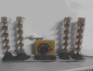
The Original Picture of the IR source in arrayed manner fixed on an aluminum foil with the camera is shown below
PROBLEMS FACED IN BUILDING THE IR SOURCE
We have faced many problems in designing and building the above shown IR source, they are listed below with explanations.
1. The first problem we faced in building the artificial LED array for IR source is the design and placement of IR LEDs. Firstly we placed IR LEDs around the camera fixed on a general purpose dot board which created difficulties in the following areas.
A. The IR LEDs placed around the camera created space congestion and so the LEDs are turning to different angles.
B. The voltage distribution model for the LEDs will be divided in to 4 Parts, The top column, the Bottom, the left and the Right. But the model failed because of the deviations in voltage Vs number of LEDs connected in series in each column.
C. Due to the voltage distribution deviation the first LED of each column started glow in red color due to high current as we have not able to find out the exact resistance to be connected in series with each column.
D. The LEDs are then placed in 4 dotted boards, each board contains 2 columns of LEDs and each column contains 5 LEDs connected in series. All the columns are connected in parallel.
E. The then issue is the correct resistance to be connected with each column.
2. The value selection of resistance is very tough in our case. Because we have to distribute
2 V and a Maximum of 2.5 V to each LED. For this we have to follow the below formula.The LEDs are working properly in our method of connection only if a 3.3 Kilo Ohm Resistor is connected in series with each LED column.
3. But the major issue in this is we can not get the exact 3.3 Kilo ohm resistor, for this we used the effective resistance formula and connected 3 numbers of 10 Kilo ohm resistors in parallel to get the exact value of 3.3 k, the formula used is given in previously.
IR FILTER ENEMY OF NIGHT VISION
All the digital cameras and mobile phone cameras are by default equipped with an IR filter in the lens assembly. The IR filter is used to avoid red eye problem in image creation by using digital cameras.
In the presence of visible light if the IR rays interfere they will create a less quality and image and also will create red dots in reflecting surfaces. To avoid these camera manufacturers should have to filter the IR rays reflected from the objects to fall on the camera image sensor.
The camera manufacturers are using a specially made glass piece in between the lens and camera image sensor to block IR rays to fall on the image sensor. For night vision camera this filter is the biggest enemy and will make the entire system to not work.
While we have built the entire system we were not aware of this IR filter an our camera have given 0 % result in the absence of visible light. but while using a mobile phone camera and analyzed the IR LEDs they are found working properly. As the mobile phone camera was kept very closer to the LEDs the intensity of the IR rays will be very high and we can see the in visible IR rays through mobile camera.
But in the principle of reflection from the objects and image capturing, it is giving 0 % result. After serious of analysis and references, we found that there is a glass piece called IR filter will be present in all cameras.
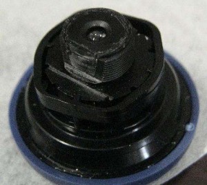
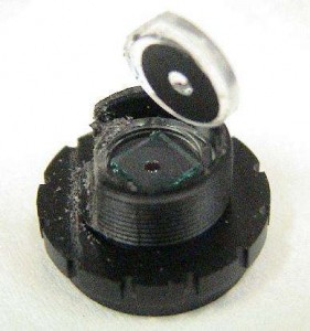
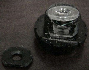
The IR filter will be present in between the Lens and image sensor. So to remove it we have to carefully operate the lens assembly and remove it.
We filed the lens assembly from one side and disassembled it. After disassembling, the IR filter was found and removed.
Once the IR filter was removed, the camera has given 100 % result in the absence of visible light.
Use the following steps to remove an IR filter from the camera lens array
The IR source Control
By default if a night vision camera is fixed on outdoors to monitor intrusion, the camera will use the sun light as light source and there is no need for IR radiations.
2. If the IR source ( LED array ) is on it will consume considerable amount of power which will reduce the battery backup.
3. To avoid this we are using a LDR based controller which will sense the lack of visible light source in the environment and switch on the IR LED array, the IR LED array will emits IR radiations which is invisible to human eyes but visible to camera.
4. When the visible light (sun light) is available in the environment the LDR will sense the same and switch off the LED array.
5. LDR is a Light Dependant Resistor whose resistance will get reduced when the visible Light falls on it and allows current to pass through it. The 555 IC is the main controller which will switch the relay on, the relay passes the 12 v current to the LED array. The IR LED array in turn emits IR rays.
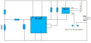
6. An electronic circuit is used to sense light and switch On or Off the IR source is. The circuit working is controlled by a 555 timer IC. The circuit diagram and explanation of its working are given below
The Circuit activates a relay upon detecting the absence of light on an Light Dependant Resistor (R3). We are using this circuit for Switching on or Off the IR – LED array for power saving purpose and image clarity in the presence of Visible light and image sensing in the absence of visible Light.
A 555 IC functions as heart of the circuit, normally the 555 IC will be operate as an astable multi vibrator or mono stable multi vibrator. But now we are using 555 IC as a Comparator.
The normal operation of the 555 IC can be described as, the output goes high upon receipt of a trigger ( Start ) pulse on input pin2. This pulse is a voltage whose level is lower than 1/3 of the supply voltage. The output goes low again when the voltage at the second input pin 6 has exceeded 2/3 of the supply level.
In principle the supply voltage for the circuit must equal to the Common input voltage of the Relay, the current consumption of the circuit is 4mA exclusive of the relay at a supply level of 12 V.
Components R2 and C1 ensure a delay of about 10 seconds before the relay is energized so that the circuit is insensitive to the rapid changes in the light intensity
Basically the circuit has no hysteresis effect. However when the supply is not regulated the actuation of the relay will lower the internal threshold of the IC since the trigger point is defined as 2/3 of the supply level (pin 2).
Therefore the hysteresis of the circuit can be dimensioned as required by fitting a resistor in series with the supply. It is also possible to fit a resistor between pins 5 and 7 of the IC 555 as shown in the circuit diagram.
The amount of hysteresis is inversely proportional to the value of the resistor and 100k is a reasonable starting point.
The sensitivity of the trigger circuit can be controlled if R1 is replaced with a 1 M Ohm Potentiometer or preset.
Note : You can purchase a kit and solder instead of struggling with making lay out and PCBs.
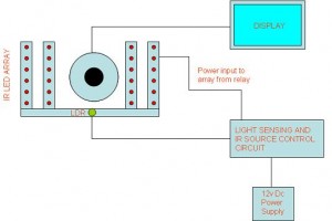
A general Over all block diagram for this system
By following the above mentioned concepts and Techniques , you can make all your cameras to be night vision enabled. Keep in mind, you need to remove your IR filter from the camera lens assembly instead the result will be the mighty ” zero “.
 Binbert Technology | Computer | Security | Networking | Mobile

Nice job , Anbarasu.
i need to design a telescopic camera…can you please help me….i need to knw how the zooming works….
Dear Sidharth,
We may make it as possible, but the thing is we should sync the IR source emitting range with the focus of the camera lens. Whenever we change the focus the range of the IR camera also should fall on the place where we are viewing.
I was also thinking to do one as you said but it needs deep knowledge in micro controller programing and long range IR source or a device that varies the range of the IR source. Will surely post once I achieve the same.